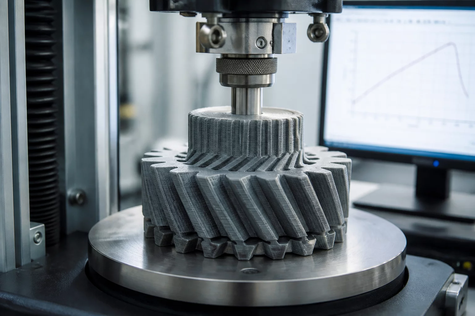
The Strategic Importance of Functional Benchmarking
Functional acceptance criteria act as the essential verification layer that separates an experimental prototype from a production-ready component. While cosmetic standards focus on visual finish, functional criteria dictate how a 3D printed part performs its intended role. Engineers must define these parameters during the design phase to prevent costly re-prints and catastrophic assembly failures.
A rigorous criteria set should avoid vague terminology like "strong enough" or "standard fit." Instead, it employs quantitative metrics that are measurable and repeatable. This approach ensures that every part coming off the printer meets the specific mechanical and thermal requirements of the project, regardless of the individual operator or machine used.
Mechanical Integrity and Load-Bearing Standards
Structural integrity is the most common functional requirement. Components must withstand specific stresses without material failure or excessive deformation. In additive manufacturing, this is complicated by anisotropy—the tendency of parts to be weaker along the Z-axis. Functional criteria must account for this by specifying the orientation in which the part was tested.
- Tensile Strength Minimums: Explicit MPa thresholds required for both horizontal and vertical axes.
- Flexural Modulus: Defined limits for bending and elastic recovery in structural brackets.
- Impact Resistance: Energy absorption capacity needed to prevent brittle fractures during operation.
Thermal and Environmental Performance
Operational environments often expose 3D printed parts to high temperatures, chemicals, or UV radiation. Functional criteria define the thermal ceiling of the material. For example, a part housing electronics must maintain its geometric stability under continuous heat exposure. If a part warps even by a fraction of a millimeter at 80°C, it fails the functional test, rendering it unsuitable for high-temperature deployments.
Environmental resistance also includes moisture absorption, especially for hydroscopic materials like Nylon. Criteria should specify post-processing steps, such as annealing or sealing, to ensure the part meets the functional durability needed for long-term service.
Fit, Interface, and Assembly
A functional part rarely exists in isolation. It must interface with bearings, fasteners, or other printed components. Geometric dimensioning and tolerancing (GD&T) become the primary tools here. Precise hole diameters, thread clearances, and mating surface flatness must be documented to ensure seamless integration. Without these strict interface requirements, the functionality of the entire assembly is compromised by a single poorly defined part.
Technical Compliance Check
-
Glass Transition Temp:
85°C - 150°C
-
Layer Adhesion Factor:
98% Nom.
-
Dimensional Deviation:
+/- 0.125mm
-
Surface Roughness:
< 12.5 Ra