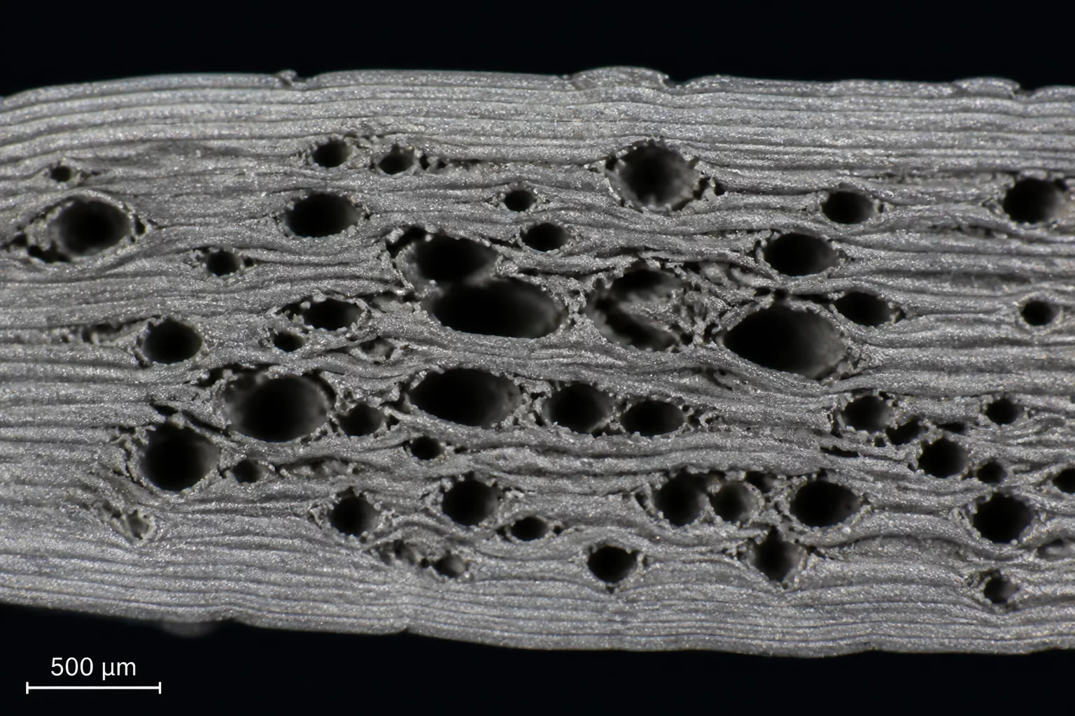
The Invisible Challenge of Internal Integrity
In additive manufacturing, a visually perfect exterior often masks a landscape of internal inconsistencies. Internal defect analysis serves as the final frontier for mission-critical parts, where a single trapped gas pore or a micron-scale lack-of-fusion void can act as a stress concentrator, leading to catastrophic failure under cyclical loading. As 3D printing transitions from prototyping to functional end-use parts in aerospace and medical sectors, understanding what lies beneath the surface has become non-negotiable for safety and performance.
Primary Categories of Sub-Surface Flaws
Identifying defects requires a clear taxonomy of their origins. We generally classify internal flaws into three high-impact categories that engineers must monitor closely:
- Gas Porosity: Small, spherical voids caused by trapped shielding gas or moisture in the feedstock material. These are common in Powder Bed Fusion (PBF) and Directed Energy Deposition (DED) processes.
- Lack of Fusion (LoF): Irregularly shaped, elongated voids that occur when the energy source fails to completely melt the powder layer or bond it to the previous layer. These are significantly more dangerous than spherical pores due to their sharp edges and high stress-concentration factors.
- Keyhole Voids: Deep, narrow cavities formed when excessive energy density causes the metal to vaporize, creating a vapor tunnel that collapses and traps gas inside the solidified track.
Advanced Diagnostic Methodologies
Traditional inspection methods often fall short when dealing with the complex internal geometries typical of 3D printing. Industrial Computed Tomography (CT) has emerged as the definitive tool for non-destructive evaluation. By capturing thousands of 2D X-ray projections and reconstructing them into a 3D volumetric model, engineers can visualize the exact location, size, and morphology of every internal void without destroying the component.
Beyond CT scanning, ultrasonic testing provides a faster, albeit less granular, alternative for identifying large discontinuities in thicker sections. For high-volume production, in-situ monitoring—which uses melt-pool thermal imaging and acoustic sensors—is increasingly used to predict where defects might form during the build process, allowing for real-time adjustments or early part rejection before expensive post-processing occurs.
Correlation Between Defect Density and Part Longevity
It is rarely possible to achieve 100% density in additive manufacturing. The goal of internal defect analysis is not always to find a perfect part, but to verify that the existing defects fall within the "Acceptance Criteria" defined during the design phase. Through fatigue testing and fracture mechanics analysis, we establish thresholds for maximum allowable pore size and proximity. If three voids are located within a specific radius of each other, they may coalesce into a crack; internal analysis is the only way to safeguard against such failure progression.