The Critical Shift from Linear to Geometric Tolerancing
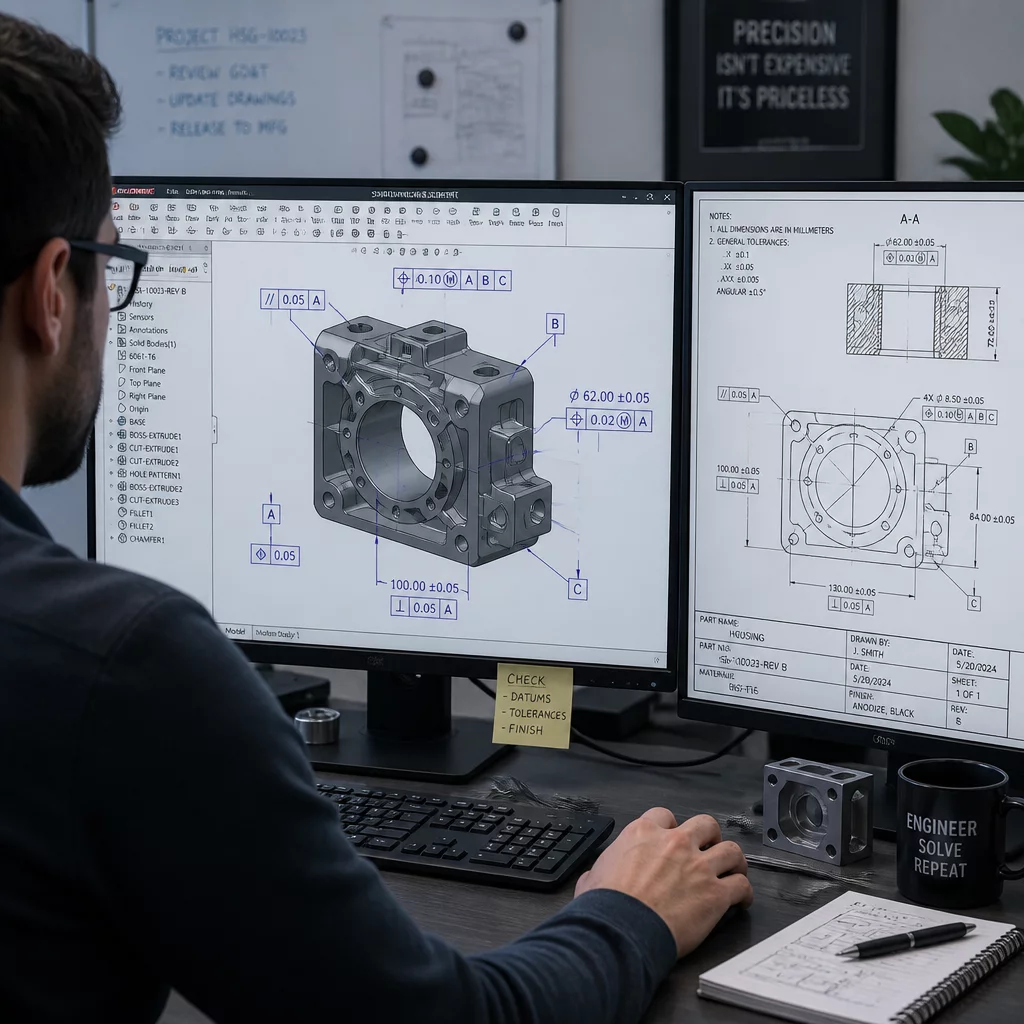
Traditional dimensioning often falls short when dealing with the organic and complex geometries produced by industrial 3D printing. Geometric Dimensioning and Tolerancing (GD&T) provides a universal language that allows engineers to communicate design intent with unmatched clarity. Instead of relying solely on +/- linear dimensions, GD&T focuses on the relationship between features, ensuring that every printed part fits perfectly into its assembly regardless of orientation or subtle print-bed variations.
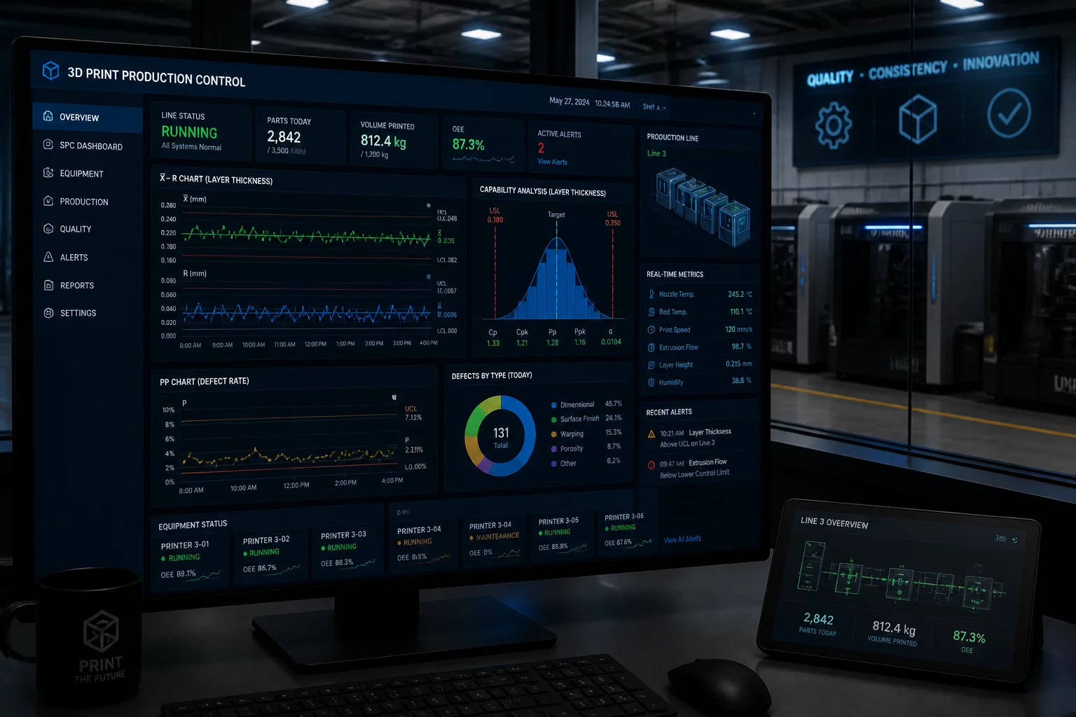
Implementing GD&T in additive manufacturing requires a deep understanding of how material shrinkage, thermal stress, and support structure removal affect final geometry. By establishing robust datum reference frames, manufacturers can accurately measure flatness, cylindricity, and position. This systematic approach reduces scrap rates and facilitates easier inspection workflows during the quality control phase, moving away from simple go/no-go checks toward data-driven process optimization.
| PARAMETER | VALUE | UNIT |
|---|---|---|
| Profile of a Surface | 0.05 - 0.15 | mm |
| Position Accuracy | Ø 0.1 | mm (at MMC) |
| Surface Flatness | 0.03 | mm |
- High-precision Coordinate Measuring Machine (CMM)
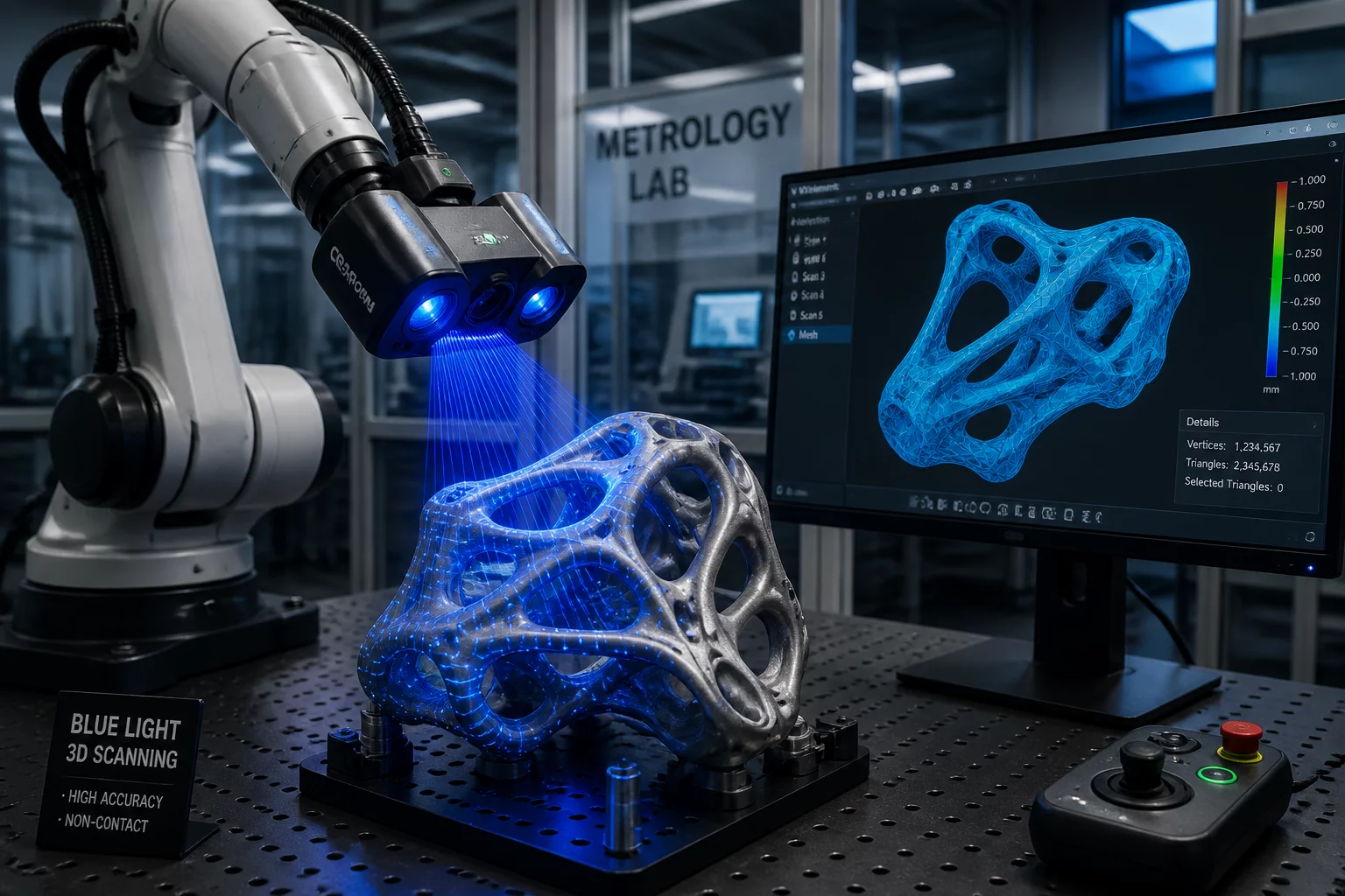
- Structured light 3D optical scanner with metrology grade sensors
- Advanced GD&T evaluation software (GOM Inspect or PolyWorks)
- Precision surface plate and calibrated height gauges for manual check
Methodology Overview
Effective verification begins with identifying functional surfaces. The first step involves defining the Primary, Secondary, and Tertiary datums based on how the part interacts with other components in its final environment. For 3D printing, it is common to use the print bed interface as a primary datum (Datum A) for raw parts, though high-accuracy applications often require a shift to post-processed features after support removal.
Symbols like Position, Profile of a Surface, and Runout are then applied to critical features within the Feature Control Frame (FCF). Verification is typically conducted by comparing the high-density point cloud from a 3D scan against the CAD nominal model. GD&T evaluation software then calculates deviations relative to the established datum reference frames, providing a visual heat map of geometric compliance across the entire surface area.