Precision Measurement in Additive Manufacturing
Metrology in the world of 3D printing faces distinct challenges compared to traditional subtractive manufacturing. The organic shapes, lattice structures, and specific surface finishes common in additive processes often render traditional contact tools insufficient. High-precision optical scanners and multi-sensor coordinate measuring machines (CMM) have become the industry standard for ensuring that every printed component aligns perfectly with its digital design intent.
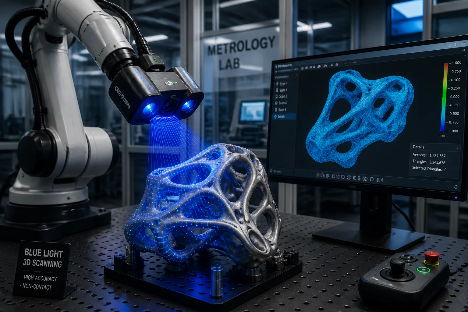
These specialized tools go beyond simple dimensional checks. They provide a comprehensive visual map of how the material has reacted to thermal cycles during the build, revealing critical issues like warping, shrinkage, or layer shifts. By utilizing non-contact structured light or high-speed laser scanning, engineers create a high-fidelity digital twin of the physical object. This data is then overlaid against the original CAD file, highlighting deviations through heatmap visualizations that pinpoint exactly where a part might be failing its specified tolerances.
| PARAMETER | VALUE | UNIT |
|---|---|---|
| Spatial Resolution | 0.010 - 0.050 | mm |
| Measurement Speed | 1.2M - 2.5M | points/sec |
| Typical Accuracy | ±0.025 | mm |
- Blue Light Structured Light Scanner (e.g., GOM/ZEISS)
- Multi-sensor Coordinate Measuring Machine (CMM)
- Surface Profilometer for Ra/Rz Analysis
- Matte Developer Spray (for reflective surfaces)
Methodology Overview
The metrology workflow starts with careful part preparation, ensuring the surface is free from debris. A scan is performed, capturing a dense point cloud that the software converts into an STL mesh. This "as-built" model is then aligned to the nominal CAD geometry using specific datums or a general "Best Fit" algorithm.
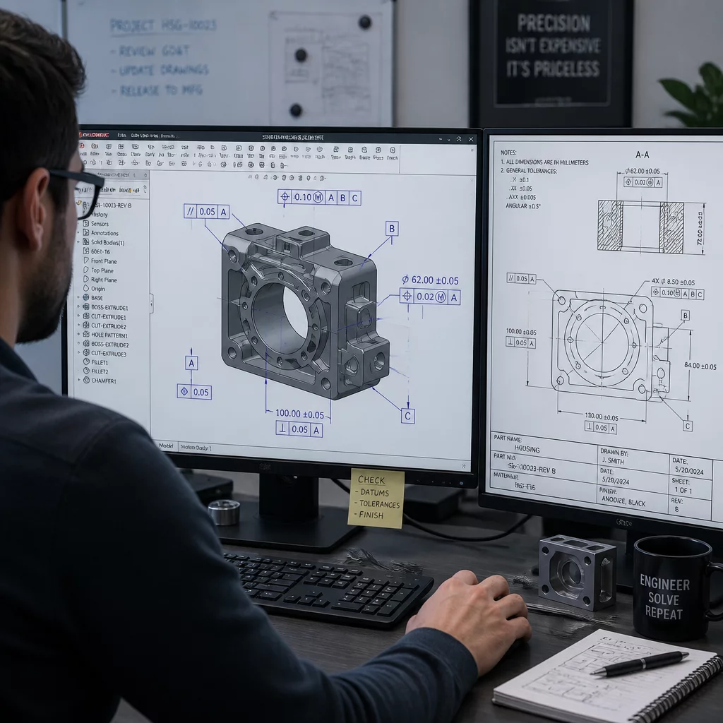
After alignment, the system generates a deviation analysis. For functional validation, engineers inspect critical features such as hole diameters, flatness, and cylindricity against established GD&T requirements. A final inspection report is generated, providing the data needed for part acceptance or for refining the additive manufacturing process to improve future yields.